
What is FSM?
- A Finite State Machine, or FSM, is a computation model that can be used to simulate sequential logic, or, in other words, to represent and control execution flow.
- Now, a sequential logic or a sequential circuit is the one that has a memory unit in it, unlike a combinational logic. It even has a clock. In simple terms, we can say it is a combinational logic along with a memory.
- Common examples of sequential circuits include registers and flip-flops.
- We have a fixed set of states that the machine can be in.
- The machine can only be in one state at a time. It means the machine has to transition from one state to another in order to perform different actions.
- A sequence of inputs is sent to the machine.
- Every state has a set of transitions and every transition is associated with an input and pointing to a state.
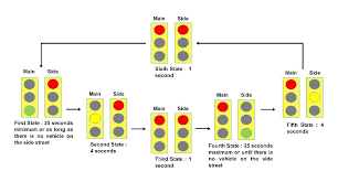
Let’s take a real-life example of a traffic light to better understand how FSM actually works-
Traffic Light
- States: Red, Yellow, Green
- Transitions: After a given time, Red will change to Green, Green to Yellow, and Yellow to Red.
The light will be only in one state at a time, and to perform the next action, it has to transition from one state to another. So, this is a case of FSM.
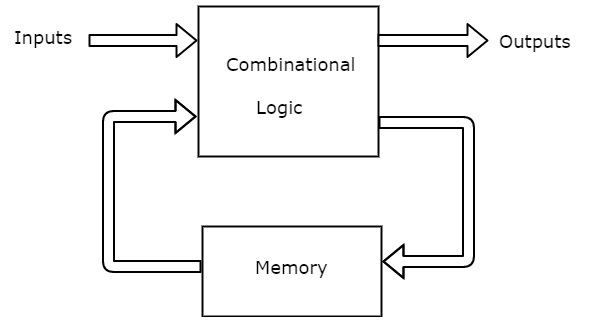
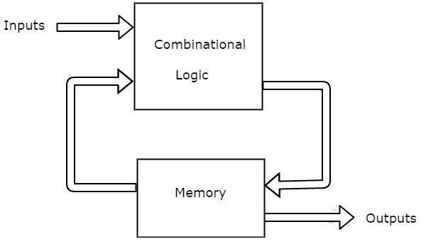
Now, if there are a finite number of states. There are two types of FSMs i.e. the Mealy State Machine and the Moore State Machine. Their basic block diagrams are shown below-
Mealy State Machine
Moore State Machine
Let’s understand both the types and write their Verilog codes, test bench and generate the output table and the waveform.
For both Mealy and Moore state machine, while writing the test benches I have taken 2 cases. First, if we directly give a set of values in the test bench, and second, we generate a set of random test values.
Mealy State Machine- It is based on both the present input and present state.
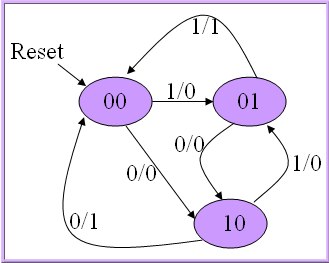
- 0/0, 1/0, 1/1, 0/1 represent input/output
- In the above figure, there are two transitions from each state based on the value of the input, x.
Also read How to write a Simple RISC Assembly Program?
Verilog Code for Mealy State Machine
mealy.v
 `timescale 1ns/1ns

module mealy(clk,rst,inp,out);

 input clk, rst, inp;

 output out;

 reg out;

 reg [1:0] state;

 always @(posedge clk, posedge rst)

 begin

     if(rst)

         begin

             out <= 0;

             state <= 2'b00;

         end

     else

         begin

             case (state)

             2'b00:

                 begin

                     if (inp) begin

                         state <=2'b01;

                         out <=0;

                     end

                     else begin

                         state <=2'b10;

                         out <=0;

                     end

                 end

             2'b01:

                 begin

                     if(inp) begin

                         state <= 2'b00;

                         out <= 1;

                     end

                     else begin

                         state <= 2'b10;

                         out <= 0;

                     end

                 end

             2'b10:

                 begin

                     if(inp) begin

                         state <= 2'b01;

                         out <= 0;

                     end

                     else begin

                         state <= 2'b00;

                         out <= 1;

                     end

                 end

             default:

                 begin

                     state <= 2'b00;

                     out <= 0;

                 end

             endcase

         end
 end

 endmodule
Testbench for Mealy State Machine: giving direct test values
mealy_tb.v
// directly test values given
`timescale 1ns/1ns
`include "mealy.v"
module mealy_tb;
wire out;
reg clk,rst,inp;
reg [15:0] seq;
integer i;
mealy instance22(clk, rst, inp, out);
initial begin
clk=0;
rst=1;
seq=16'b1010_0001_1100_0101;
#5 rst=0;
end
always begin
$dumpfile("mealy_direct.vcd");
$dumpvars();
for( i = 0; i <= 15; i = i+1)
begin
inp = seq[i];
#2 clk=1;
#2 clk=0;
$display("state = ",instance22.state,"| input = ",inp,"| output = ",out);
end
#100 $finish();
end
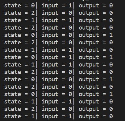
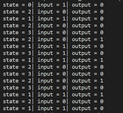
endmodule Output Table for Mealy State Machine: giving direct test values
The table includes 3 columns. The first one tells the current state. We have three possible states 0, 1, and 2. The next column is for displaying input which can be either 0 or 1. These inputs are the ones given by us in the testbench as a sequence.
The last is the output column for each specific input.
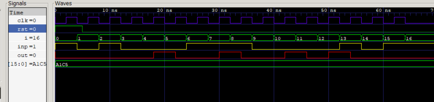
The waveform for Mealy State Machine: giving direct test values
Testbench for Mealy State Machine: generating random test values
mealy_tb_2.v
// randomly generated test values given
`timescale 1ns/1ns
`include "mealy.v"
module mealy_tb_2;
wire out;
reg clk,rst,inp;
integer i;
mealy instance22(clk, rst, inp, out);
initial begin
clk=0;
rst=1;
#5 rst=0;
end
always begin
$dumpfile("mealy_random.vcd");
$dumpvars();
for( i = 0; i <= 15; i = i+1)
begin
inp = $random % 2;
#2 clk=1;
#2 clk=0;
$display("state = ",instance22.state,"| input = ",inp,"| output = ",out);
end
#100 $finish();
end
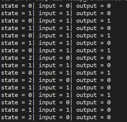
endmodule Output Table for Mealy State Machine: generating random test values
Here, the inputs are generated randomly using a for loop.
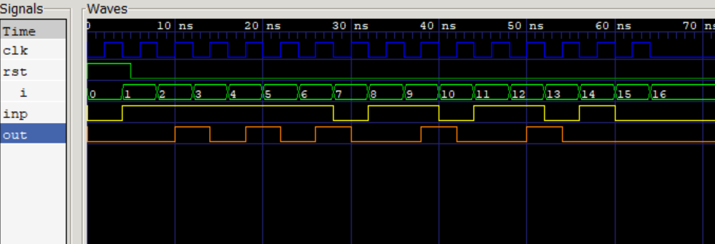
The waveform for Mealy State Machine: generating random test values
Moore State Machine – It is based only on the present state and not on the present input.
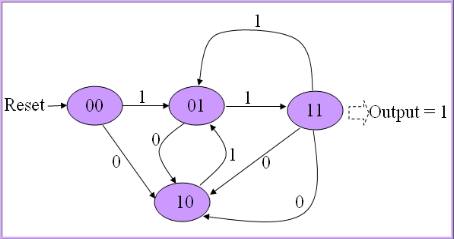
- There are two transitions from each state based on the value of the input, x.
Verilog Code for Moore State Machine
moore.v
 `timescale 1ns/1ns

module moore(clk,rst,inp,out);

 output out;

 input clk, rst, inp;

 reg out;

 reg [1:0] state;

 always @(posedge clk, posedge rst)

     begin

         if(rst)

             begin

                 state <= 2'b00;


             end

         else

             begin

                 case(state)

                     2'b00: begin

                         if(inp) begin

                             state <= 2'b01;

                         end

                         else begin

                             state <= 2'b10;

                         end

                     end

                     2'b01: begin

                         if(inp) begin

                             state <= 2'b11;

                         end

                         else begin

                             state <= 2'b10;

                         end

                     end

                     2'b10: begin

                         if(inp) begin

                             state <= 2'b01;

                         end

                         else begin

                             state <= 2'b11;

                         end

                     end


                     2'b11: begin

                         if(inp) begin

                             state <= 2'b01;

                         end

                         else begin

                             state <= 2'b10;

                         end

                     end

                     default: begin

                         state <= 2'b00;

                     end

                 endcase

             end

     end

     always @(posedge clk, posedge rst)

         begin

             if(rst) begin

                 out <= 0;

             end

             else if (state == 2'b11) begin

                 out <= 1;

             end

             else begin

                 out <= 0;

             end

         end

 endmodule
Testbench for Moore State Machine: giving direct test values
moore_tb.v
 // directly test values given

`timescale 1ns/1ns

 `include "moore.v"

 module moore_tb;

 wire out;

 reg clk,rst,inp;

 reg [15:0] seq;

 integer i;

 moore instance22(clk, rst, inp, out);

 initial begin

     clk=0;

     rst=1;

     seq=16'b1010_0001_1100_0101;

     #5 rst=0;

 end

 always begin

     $dumpfile("moore_direct.vcd");

             $dumpvars();

     for( i = 0; i <= 15; i = i+1)

         begin

             inp = seq[i];

             #2 clk=1;

             #2 clk=0;

             $display("state = ",instance22.state,"| input = ",inp,"| output = ",out);

         end

     #100 $finish();

 end

 endmodule
Output Table for Moore State Machine: giving direct test values
As in the case of the Mealy State Machine, here we give a 16-bit sequence for input values consisting of only 0’s and 1’s.
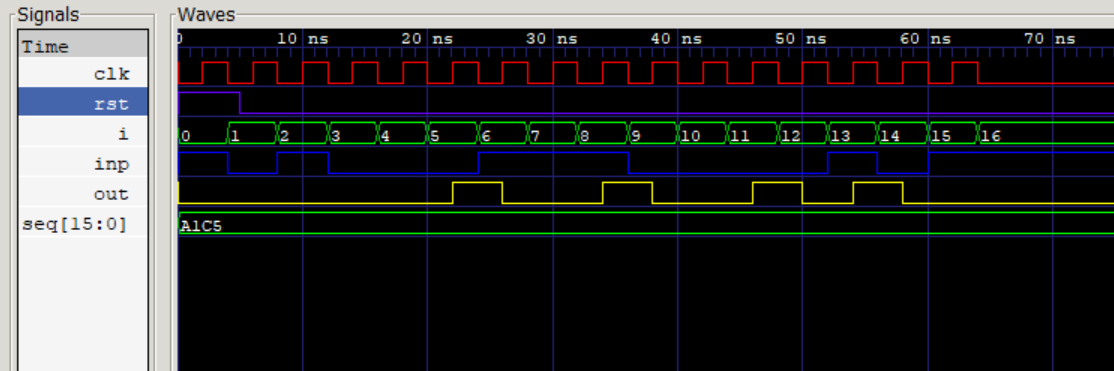
The waveform for Moore State Machine: giving direct test values
Testbench for Moore State Machine: generating random test values
moore_tb_2.v
// randomly generated test values given
`timescale 1ns/1ns
`include "moore.v"
module moore_tb_2;
wire out;
reg clk,rst,inp;
integer i;
moore instance22(clk, rst, inp, out);
initial begin
clk=0;
rst=1;
#5 rst=0;
end
always begin
$dumpfile("moore_random.vcd");
$dumpvars();
for( i = 0; i <= 15; i = i+1)
begin
inp = $random % 2;
#2 clk=1;
#2 clk=0;
$display("state = ",instance22.state,"| input = ",inp,"| output = ",out);
end
#100 $finish();
end
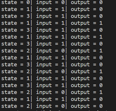
endmodule Output Table for Moore State Machine: generating random test values
In this case, values for input are randomly generated using the for loop. This is done 16 times to get a long sequence.
The waveform for Moore State Machine: generating random test values

This was all about FSM and its types for finite states, namely the Mealy and Moore State Machine.